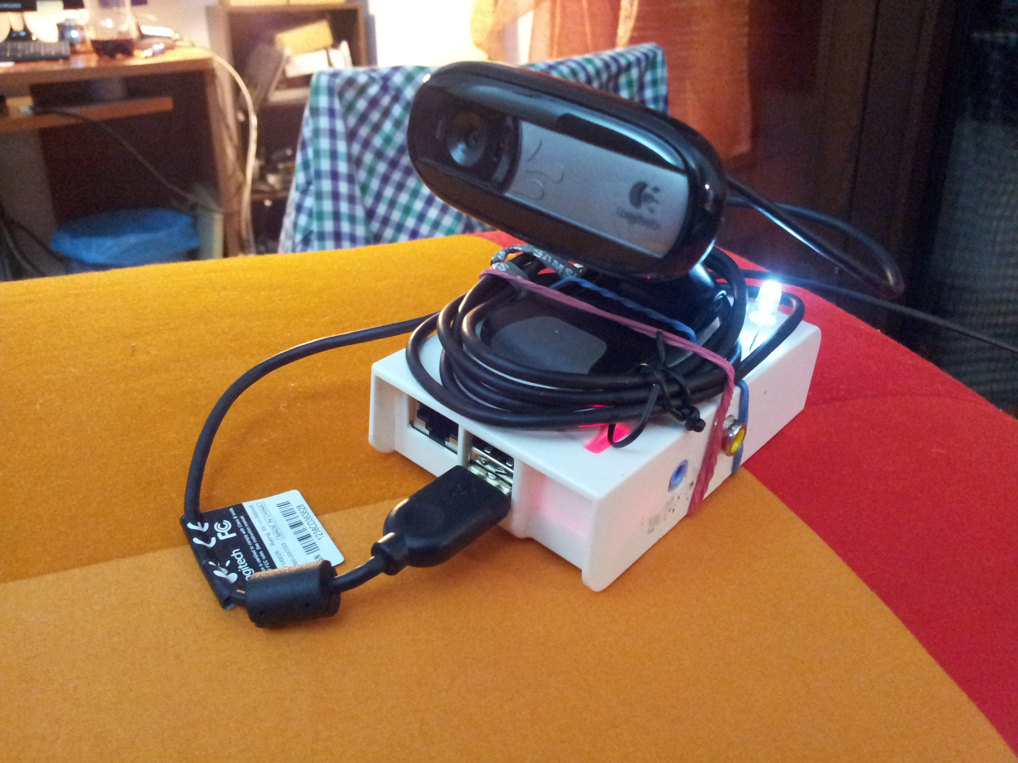
The Shotter is one of my first project I used the Raspberry for, and the idea is very simple: using a Raspberry PI and a webcam to take a photo every n seconds, and eventually mounting a video from the taken frames.
I made this with one of my PIs, and i configured it to automatically start taking the photos when I plug a usb drive, and to save the photos directly to the key. If you want to stop it, you just unplug the usb key or switch off the power. The photos are saved with an alphabetical friendly format, that is a increasing number padded with zeros: ‘00000001.jpg’, ‘00000002.jpg’, … This makes easy to make the final video, for example with mencoder:
The photos have a small size, about 70-80KB, so that a 1Gb usb key can handle more than one day of photos taken every 10 seconds.
I also added a led to the PI, which it’s blinking when the PI is waiting for the timeout to expire, just to say that everything is working fine (it’s been very useful while debugging).
Here are some videos I made with my shotter:
I think it’s great for taking photos during a party (I did it but I won’t publish the video here 🙂 )
Here’s a stupid python code to do the job (launched by a usbmount script, see this other post where I explain something more about usbmount or just search the Internet)
import sys
import time
import os
import RPi.GPIO as GPIO

GPIO.setmode(GPIO.BOARD)
GPIO.setup(22,GPIO.OUT)

def getIndex():
    try:
        f = open('/home/pi/shotter_service/index', 'r')
        text = f.read()
        f.close()
        index = int(text)
    except:
        index = 0
        setIndex(0)
    return index

def setIndex(index):
    f = open('/home/pi/shotter_service/index', 'w')
    f.write(str(index))
    f.close()

def padding(what, length):
    what = str(what)
    for i in range(length - len(what)):
        what = "0" + what
    return what

dev = 0
secs = 10
version = "0.1"
index = getIndex()

state = False

if len(sys.argv) > 1:
  dev = int(sys.argv[1])

if len(sys.argv) > 2:
  secs = int(sys.argv[2])
while True:
  setIndex(index+1)
  print "Current Index is " + str(index)
  os.system("fswebcam -r 640x480 -S 15 --subtitle "Daniele Nicassio's Projects" --banner-colour 80000000 --line-colour 00FFFFFF --title "Raspberry PI Shotter "+version+"" --info "https://www.nicassio.it/daniele/blog" --no-timestamp --jpeg 95 -d /dev/video"+str(dev) + " --save /media/usb0/""+padding(index, 10)+".jpg"")
  os.system("sync")
  index += 1
  for i in range(secs):
    state = not state
    GPIO.output(22, state)
    time.sleep(1)
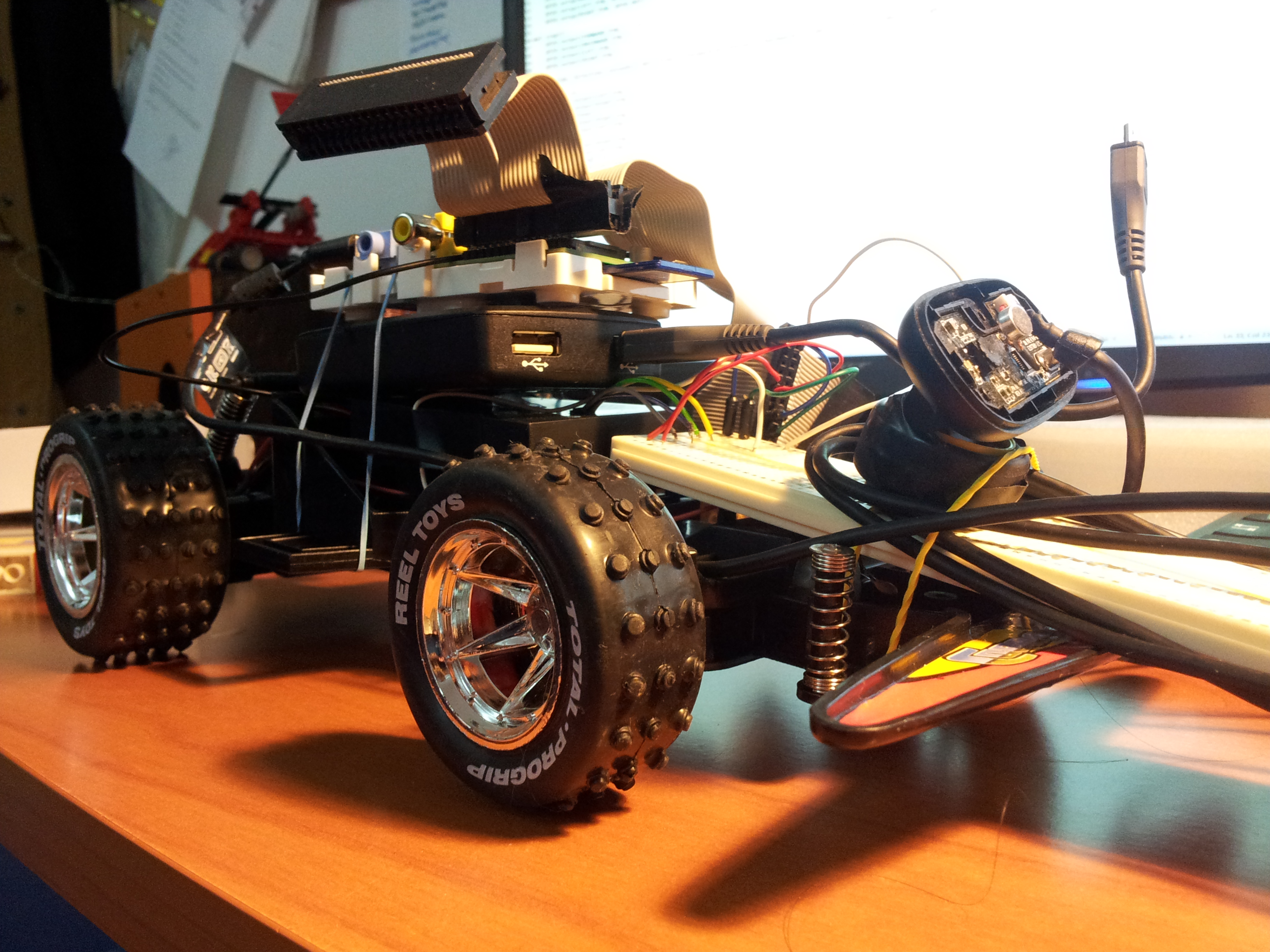
This video shows a cheap RC car hacked to be controlled by the Raspberry PI. It is completely autonomous, it uses a webcam to turn and point the light. The computation is made with the OpenCV libraries.
Today i’m going to write about my new project, a Raspberry PI powered radio car. For now it can provide only basic functionalities, but it can be easily improved by upgrading the software, on which i didn’t focus very much so far.
In this post i will explain how I configured the PI to accomplish the task.
What I used in this project?
a Raspberry PI
a standard 16×2 character LCD display (HDD44780 compatible)
usb speakers
a button
a wheel from an old mouse
a box
The idea
The idea is to make a car radio capable of playing music from a usb pen plugged in the PI. My radio can only shuffle the songs found, but that’s just about software, it can be improved in many ways, that is where a lot of customization may take place.
Getting the display working with the PI
The first thing to do is to understand how to drive the LCD display from the PI. This is made by connecting the display to the PI’s GPIO, and then sending the commands from the programming language, usually using a library for the HDD44780 standard.
After I was able to write to the display, I wrote a little python script to print something to the display from the command line, which could be useful to write something to the lcd from a shell script later:
To play music through a USB device, the PI must be configured properly. In my case, I had some operation to do before everything worked, and my speakers are still showing some problems when playing from the PI (I hear a little noise, but i didn’t search enough to tell it can’t be resolved).
Anyway, if you want to use your PI as a car radio, you probably want the USB speakers to be the default audio device for it. You can do this by editing the /etc/modprobe.d/alsabase.conf adding the following line, or modifying the relative line if it already exists with another value (which in raspbian should be the case):
options snd-usb-audio index=0
I had also another problem which seemed to be quite common, and I also had to add another line at the end of that file, to avoid an “expected delay” error which I discovered running dmesg:
options snd-usb-audio nrpacks=3
I choose the higher value which didn’t give me errors in the log. After modifying the file i restarted alsa with
sudo service alsa-utils restart
This wasn’t enough to play music through the speakers, I also had to specify the right device when i played the music with mplayer. I had to discover the name of the device running the following command:
aplay -L
which gives a list of the recognized devices, from which i selected the right one, and finally got mplayer to play some mp3s:
mplayer -ao alsa:device=front my_music_file.mp3
Usb automount and autoplay
Now that the display is working correctly and we can play music through the speakers, let’s figure out how to handle the mounting/umounting actions:
The next step is to configure the PI to automatically mount any usb drive plugged in. This can be done by using the usbmount software avaiable in the raspbian repository:
sudo apt-get install usbmount
Now, I want to autoplay music when the usb is plugged in, so I add a custom script to the default usbmount script folder /etc/usbmount/mount.d :
#!/bin/bash

python /home/pi/lcd/char/print.py "Madre foca:

Playing music.."

sudo -u pi mplayer -slave -input file=/home/pi/fifofile -ao alsa:device=front -shuffle $UM_MOUNTPOINT/* $UM_MOUNTPOINT/*/* $UM_MOUNTPOINT/*/*/*
The first command uses the python script I created before to print something to the LCD when music is starting, while the third line starts the playback.
As you can guess, the $UM_MOUNTPOINT variable contains the path to the mounted drive.
The -slave mplayer option is a very useful way to let you send commands to mplayer even if it’s backgrounded. It tells mplayer to read input commands from a file, but if we provide a fifo file instead of a normal one, mplayer will read from it only when we will write something. This allows mplayer to be controlled by writing to a file, from python, shell or whatever you prefer. To create a fifo file you should use
mkfifo /home/pi/fifofile
If you want to know more on the -slave option of mplayer, see here.
I had to add the sudo -u pi part because it seemed that the user of usbmount wasn’t allowed to read from the fifo, I don’t know exactly why.
Finally, I also created a script for the umount event, which simply killed mplayer, and placed it in the /etc/usbmount/umount.d directory:
#!/bin/bash

python /home/pi/lcd/char/print.py "Music stopped.

I'm a super PI."

killall mplayer
Connecting the inputs: the button and the wheel
I’m not very good with electronics, so i won’t explain this part very deeply, also because that’s pretty basic.
The scheme to read the state of a button should be something like this:
The mouse wheel should have three connectors, and it behave like two button together, with the central pin in common. The only thing to know about it is that the two “buttons” are switched on and off while you turn the wheel, but one of them is triggered a little before the other, giving you information about the direction.
I decided to use a wheel (or two button) and an additional button to provide basic input for a “menu” structured OS for the radio, which is the minimal input for a fair usability.
Reacting to the inputs
The last thing to do is to react to the input of the user, writing the real “operating system” for our radio. I wrote this in python, and the interface is really minimal, providing the wheel to control the volume and the button to skip to the next song.
As usual the code is really bad written, and it should be used only to understand how it works. I encourage you to write a real interface, you could really do anything with that.
The script (bad written of course) is this:
import RPi.GPIO as GPIO
import time
import os
from Adafruit_CharLCD import Adafruit_CharLCD

lcd = Adafruit_CharLCD()
lcd.begin(16,1)
lcd.clear()
lcd.message("Hello!nI'm the SuperPI.")

def left():
    lcd.clear()
    lcd.message("Volume up")
    os.system("amixer set PCM 5+");
    print "left"

def right():
    lcd.clear()
    lcd.message("Volume down")
    os.system("amixer set PCM 5-");
    print "right"

def pressed():
    print "pressed"
    lcd.clear()
    lcd.message("Skipping tonnext song")
    f = open('/home/pi/fifofile','w')
    f.write('seek 100 1n')
    f.close()

GPIO.setmode(GPIO.BCM)
GPIO.setup(4, GPIO.IN)
GPIO.setup(18,GPIO.IN)
GPIO.setup(2,GPIO.IN)

last_a = False
last_b = False
last_c = True
paired = True
i=0
while True:
    a = GPIO.input(4)
    b = GPIO.input(18)
    c = GPIO.input(2)
    #print "4: "+str(a)+ " 18: " + str(b)
    if c == False and c != last_c:
        pressed()

    if a != b and paired:
        if a != last_a:
            left()
        else:
            right()
        paired = False
    else:
        paired = True
    i+=1
    last_a = a
    last_b = b
    last_c = c
    time.sleep(0.01)
Note that it uses the previous created fifo to send to mplayer the command to skip to the next song.
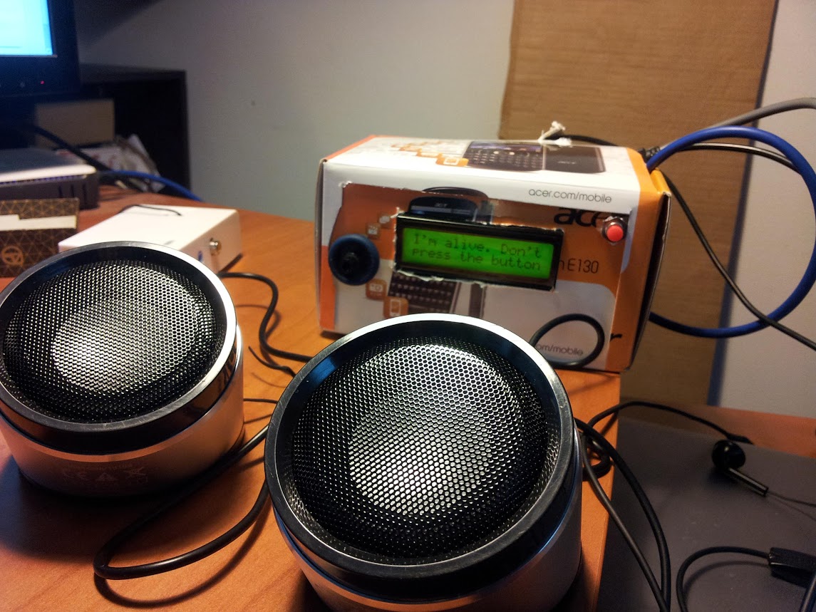
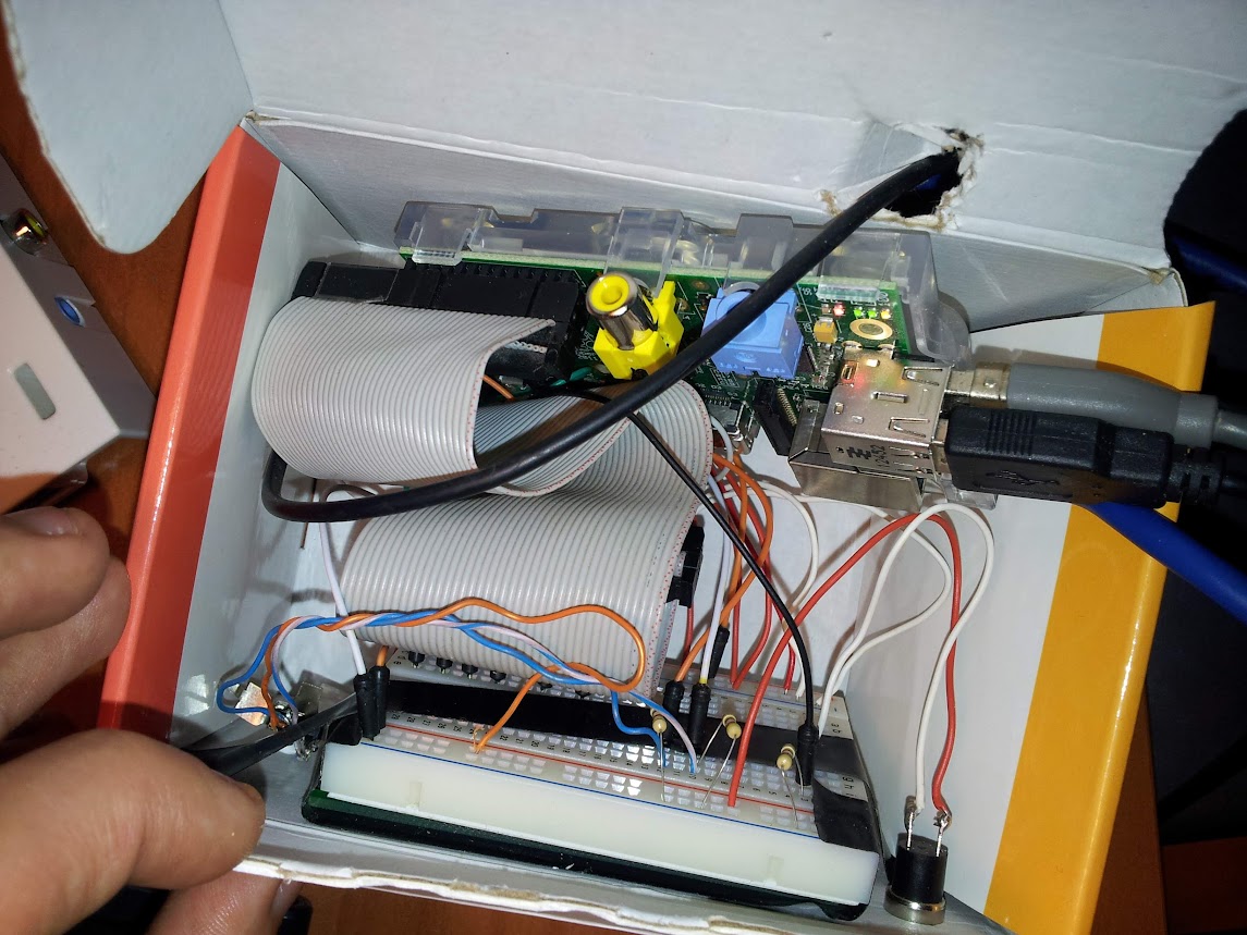
Assembling
I’m sure that anyone can assemble this project better than I did. And to prove it i’ll show a picture:
The video
Here’s a little video (in italian) in which I show the (few) functionalities of the radio:
I’m thinking, when I have some spare time, to extend its functions by attaching a webcam and trying to do something more complex, given the wide range of possibilities the PI can offer.
When i read about turning your Raspberry PI into a FM transmitter i was really excited. That’s real hacking!
I decided to try to use this hack to provide an aux input for car radio which doesn’t have it, and i succeeded (quite well).
I downloaded the FM transmitter C program from the link above and figured out a way to drive my usb audio card mic input to the program, to be able to broadcast that in FM: wonderful.
The result was a short range Raspberry PI powered FM transmitter, and i was able to tune my radio to the right frequency (in this case 100.00 MHz) and to listen for the music i was playing from my device.
Since there has been some interest about how I made this, I post here the little scripts I wrote for this project, even if they are not written very well, and may not be easy to understand and adapt to your needs. Here they are: