In these months, I attended course of Computability and Complexity, ending with some concepts of cryptography.
It’s been really interesting, so I wanted to experiment something about it.
I created a little web page using Angular.JS and just a little PHP, to implement some kind of “secure chat”, which uses a given passphrase to encrypt every message directly on the client, and then stores the messages in an online database. This chat can host multiple users with the same passphrase, which will be able to see each other messages, doing all the encryption/decription on the client side.
This means that all the traffic going through the internet has already been encrypted, so everything is stored in the database must be decrypted with the key to be read. In theory, even accessing to the database wouldn’t give any information about the messages sent through the chat.
I really don’t know exactly how commercial messaging systems do work, but I always suspected that if the provider of the service wanted to, it would be able to read the messages going through its servers, because the ‘secure’ connection (if any) is established between the server and the clients, and not between the very two endpoints of the communication.
In the system I implemented, instead, the server makes only the ‘buffering’ of the data, it never gets in touch with the encryption keys, so that it can’t read the messages it saves to the database.
I don’t really believe commercial systems work exactly that way, but the doubt was enough to get me developing this little project 🙂
The software uses the encryption standard AES, implemented in javascript with Crypto-JS.
The AES encryption is a simmetric key encryption, which means that every user share a secret key and then use it to encrypt the data sent through an unsecure channel.
Here’s the link to the chat, if you want to be sure i’m not reading your messages in the database, you should inspect the javascript of the page, understanding that the encryption is made with your passphrase, in the client side of the application. This should be enough to understand I can’t read anything without the key.
My experiments with genetic programming are going on. I’m trying to focus on something more useful, so I’ve made a little page which uses gp to search the shortest path to connect a number of points, randomly generated, or specified by the user.
It is possible to modify the parameters of the genetic algorithm, editing the JSON object in the textarea.
I started reading something about genetic programming, and i must say it’s really interesting. I decided to try to implement a genetic algorithm just to go deeper and better understand how it works, so i developed a little gp evolving enviroment.
Everything in that page is really messed up, and it doesn’t completely work for now: anyway, if you want to give it a try, it’s here.
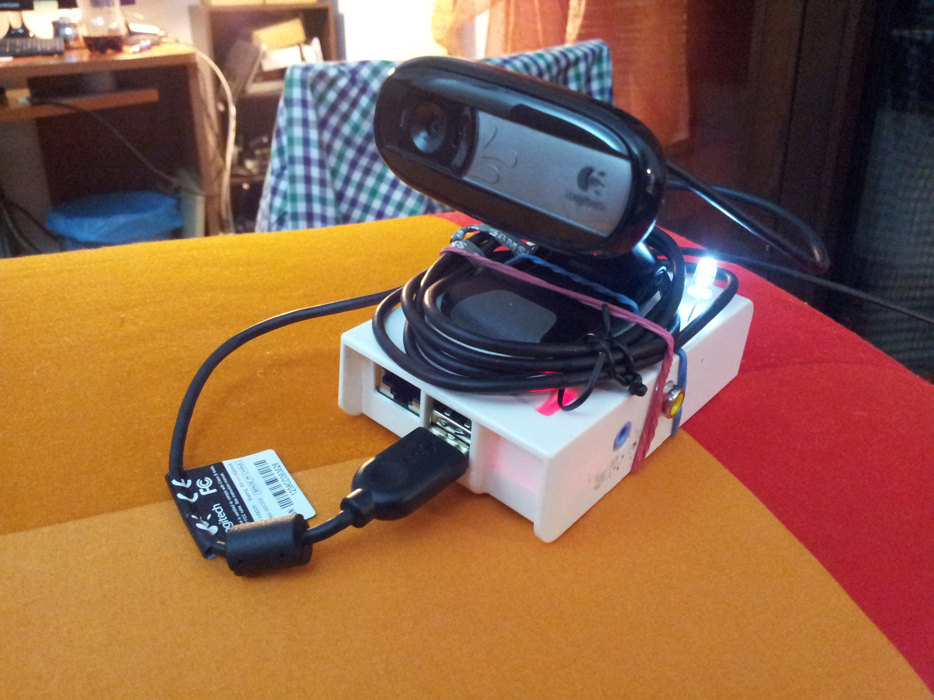
The Shotter is one of my first project I used the Raspberry for, and the idea is very simple: using a Raspberry PI and a webcam to take a photo every n seconds, and eventually mounting a video from the taken frames.
I made this with one of my PIs, and i configured it to automatically start taking the photos when I plug a usb drive, and to save the photos directly to the key. If you want to stop it, you just unplug the usb key or switch off the power. The photos are saved with an alphabetical friendly format, that is a increasing number padded with zeros: ‘00000001.jpg’, ‘00000002.jpg’, … This makes easy to make the final video, for example with mencoder:
The photos have a small size, about 70-80KB, so that a 1Gb usb key can handle more than one day of photos taken every 10 seconds.
I also added a led to the PI, which it’s blinking when the PI is waiting for the timeout to expire, just to say that everything is working fine (it’s been very useful while debugging).
Here are some videos I made with my shotter:
I think it’s great for taking photos during a party (I did it but I won’t publish the video here 🙂 )
Here’s a stupid python code to do the job (launched by a usbmount script, see this other post where I explain something more about usbmount or just search the Internet)
import sys
import time
import os
import RPi.GPIO as GPIO

GPIO.setmode(GPIO.BOARD)
GPIO.setup(22,GPIO.OUT)

def getIndex():
    try:
        f = open('/home/pi/shotter_service/index', 'r')
        text = f.read()
        f.close()
        index = int(text)
    except:
        index = 0
        setIndex(0)
    return index

def setIndex(index):
    f = open('/home/pi/shotter_service/index', 'w')
    f.write(str(index))
    f.close()

def padding(what, length):
    what = str(what)
    for i in range(length - len(what)):
        what = "0" + what
    return what

dev = 0
secs = 10
version = "0.1"
index = getIndex()

state = False

if len(sys.argv) > 1:
  dev = int(sys.argv[1])

if len(sys.argv) > 2:
  secs = int(sys.argv[2])
while True:
  setIndex(index+1)
  print "Current Index is " + str(index)
  os.system("fswebcam -r 640x480 -S 15 --subtitle "Daniele Nicassio's Projects" --banner-colour 80000000 --line-colour 00FFFFFF --title "Raspberry PI Shotter "+version+"" --info "https://www.nicassio.it/daniele/blog" --no-timestamp --jpeg 95 -d /dev/video"+str(dev) + " --save /media/usb0/""+padding(index, 10)+".jpg"")
  os.system("sync")
  index += 1
  for i in range(secs):
    state = not state
    GPIO.output(22, state)
    time.sleep(1)
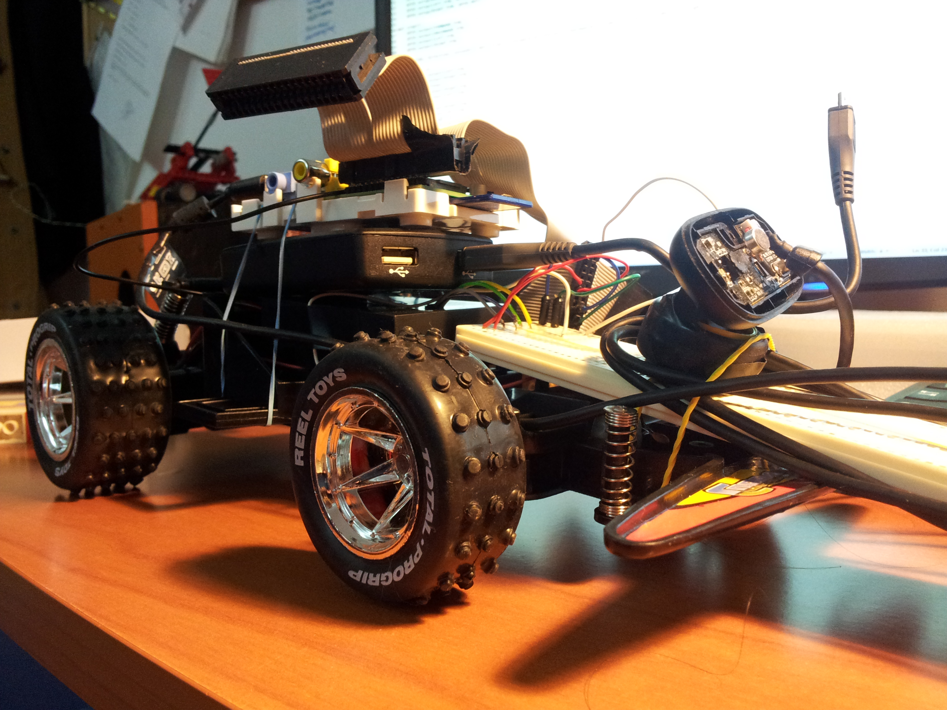
This video shows a cheap RC car hacked to be controlled by the Raspberry PI. It is completely autonomous, it uses a webcam to turn and point the light. The computation is made with the OpenCV libraries.
Today i’m going to write about my new project, a Raspberry PI powered radio car. For now it can provide only basic functionalities, but it can be easily improved by upgrading the software, on which i didn’t focus very much so far.
In this post i will explain how I configured the PI to accomplish the task.
What I used in this project?
a Raspberry PI
a standard 16×2 character LCD display (HDD44780 compatible)
usb speakers
a button
a wheel from an old mouse
a box
The idea
The idea is to make a car radio capable of playing music from a usb pen plugged in the PI. My radio can only shuffle the songs found, but that’s just about software, it can be improved in many ways, that is where a lot of customization may take place.
Getting the display working with the PI
The first thing to do is to understand how to drive the LCD display from the PI. This is made by connecting the display to the PI’s GPIO, and then sending the commands from the programming language, usually using a library for the HDD44780 standard.
After I was able to write to the display, I wrote a little python script to print something to the display from the command line, which could be useful to write something to the lcd from a shell script later:
To play music through a USB device, the PI must be configured properly. In my case, I had some operation to do before everything worked, and my speakers are still showing some problems when playing from the PI (I hear a little noise, but i didn’t search enough to tell it can’t be resolved).
Anyway, if you want to use your PI as a car radio, you probably want the USB speakers to be the default audio device for it. You can do this by editing the /etc/modprobe.d/alsabase.conf adding the following line, or modifying the relative line if it already exists with another value (which in raspbian should be the case):
options snd-usb-audio index=0
I had also another problem which seemed to be quite common, and I also had to add another line at the end of that file, to avoid an “expected delay” error which I discovered running dmesg:
options snd-usb-audio nrpacks=3
I choose the higher value which didn’t give me errors in the log. After modifying the file i restarted alsa with
sudo service alsa-utils restart
This wasn’t enough to play music through the speakers, I also had to specify the right device when i played the music with mplayer. I had to discover the name of the device running the following command:
aplay -L
which gives a list of the recognized devices, from which i selected the right one, and finally got mplayer to play some mp3s:
mplayer -ao alsa:device=front my_music_file.mp3
Usb automount and autoplay
Now that the display is working correctly and we can play music through the speakers, let’s figure out how to handle the mounting/umounting actions:
The next step is to configure the PI to automatically mount any usb drive plugged in. This can be done by using the usbmount software avaiable in the raspbian repository:
sudo apt-get install usbmount
Now, I want to autoplay music when the usb is plugged in, so I add a custom script to the default usbmount script folder /etc/usbmount/mount.d :
#!/bin/bash

python /home/pi/lcd/char/print.py "Madre foca:

Playing music.."

sudo -u pi mplayer -slave -input file=/home/pi/fifofile -ao alsa:device=front -shuffle $UM_MOUNTPOINT/* $UM_MOUNTPOINT/*/* $UM_MOUNTPOINT/*/*/*
The first command uses the python script I created before to print something to the LCD when music is starting, while the third line starts the playback.
As you can guess, the $UM_MOUNTPOINT variable contains the path to the mounted drive.
The -slave mplayer option is a very useful way to let you send commands to mplayer even if it’s backgrounded. It tells mplayer to read input commands from a file, but if we provide a fifo file instead of a normal one, mplayer will read from it only when we will write something. This allows mplayer to be controlled by writing to a file, from python, shell or whatever you prefer. To create a fifo file you should use
mkfifo /home/pi/fifofile
If you want to know more on the -slave option of mplayer, see here.
I had to add the sudo -u pi part because it seemed that the user of usbmount wasn’t allowed to read from the fifo, I don’t know exactly why.
Finally, I also created a script for the umount event, which simply killed mplayer, and placed it in the /etc/usbmount/umount.d directory:
#!/bin/bash

python /home/pi/lcd/char/print.py "Music stopped.

I'm a super PI."

killall mplayer
Connecting the inputs: the button and the wheel
I’m not very good with electronics, so i won’t explain this part very deeply, also because that’s pretty basic.
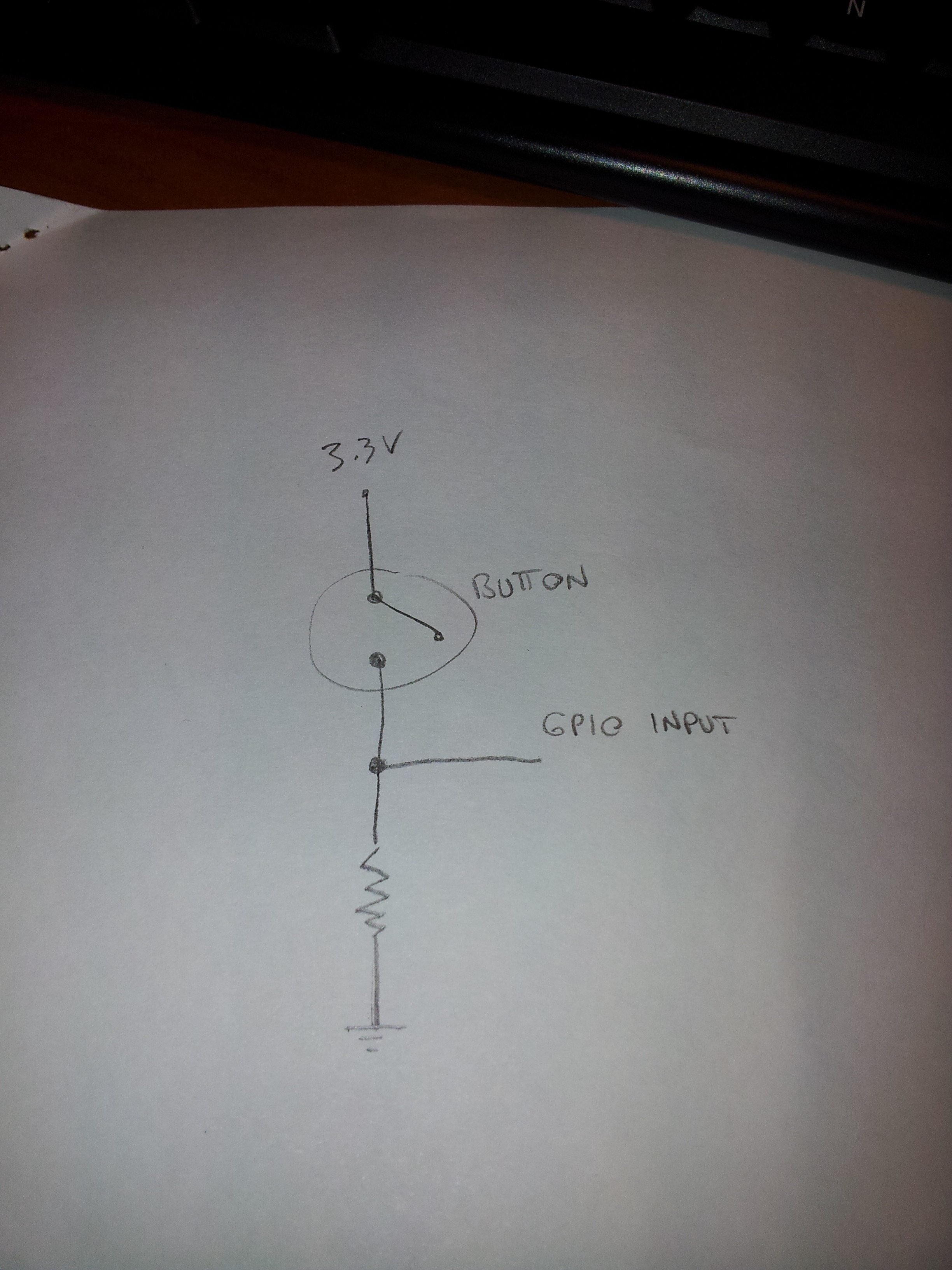
The scheme to read the state of a button should be something like this:
The mouse wheel should have three connectors, and it behave like two button together, with the central pin in common. The only thing to know about it is that the two “buttons” are switched on and off while you turn the wheel, but one of them is triggered a little before the other, giving you information about the direction.
I decided to use a wheel (or two button) and an additional button to provide basic input for a “menu” structured OS for the radio, which is the minimal input for a fair usability.
Reacting to the inputs
The last thing to do is to react to the input of the user, writing the real “operating system” for our radio. I wrote this in python, and the interface is really minimal, providing the wheel to control the volume and the button to skip to the next song.
As usual the code is really bad written, and it should be used only to understand how it works. I encourage you to write a real interface, you could really do anything with that.
The script (bad written of course) is this:
import RPi.GPIO as GPIO
import time
import os
from Adafruit_CharLCD import Adafruit_CharLCD

lcd = Adafruit_CharLCD()
lcd.begin(16,1)
lcd.clear()
lcd.message("Hello!nI'm the SuperPI.")

def left():
    lcd.clear()
    lcd.message("Volume up")
    os.system("amixer set PCM 5+");
    print "left"

def right():
    lcd.clear()
    lcd.message("Volume down")
    os.system("amixer set PCM 5-");
    print "right"

def pressed():
    print "pressed"
    lcd.clear()
    lcd.message("Skipping tonnext song")
    f = open('/home/pi/fifofile','w')
    f.write('seek 100 1n')
    f.close()

GPIO.setmode(GPIO.BCM)
GPIO.setup(4, GPIO.IN)
GPIO.setup(18,GPIO.IN)
GPIO.setup(2,GPIO.IN)

last_a = False
last_b = False
last_c = True
paired = True
i=0
while True:
    a = GPIO.input(4)
    b = GPIO.input(18)
    c = GPIO.input(2)
    #print "4: "+str(a)+ " 18: " + str(b)
    if c == False and c != last_c:
        pressed()

    if a != b and paired:
        if a != last_a:
            left()
        else:
            right()
        paired = False
    else:
        paired = True
    i+=1
    last_a = a
    last_b = b
    last_c = c
    time.sleep(0.01)
Note that it uses the previous created fifo to send to mplayer the command to skip to the next song.
Assembling
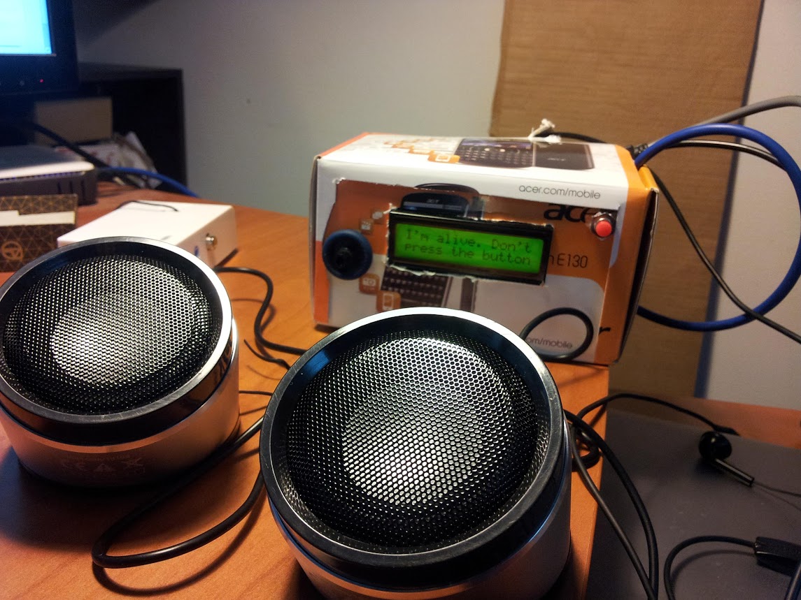
I’m sure that anyone can assemble this project better than I did. And to prove it i’ll show a picture:
The video
Here’s a little video (in italian) in which I show the (few) functionalities of the radio:
I’m thinking, when I have some spare time, to extend its functions by attaching a webcam and trying to do something more complex, given the wide range of possibilities the PI can offer.
When i read about turning your Raspberry PI into a FM transmitter i was really excited. That’s real hacking!
I decided to try to use this hack to provide an aux input for car radio which doesn’t have it, and i succeeded (quite well).
I downloaded the FM transmitter C program from the link above and figured out a way to drive my usb audio card mic input to the program, to be able to broadcast that in FM: wonderful.
The result was a short range Raspberry PI powered FM transmitter, and i was able to tune my radio to the right frequency (in this case 100.00 MHz) and to listen for the music i was playing from my device.
Since there has been some interest about how I made this, I post here the little scripts I wrote for this project, even if they are not written very well, and may not be easy to understand and adapt to your needs. Here they are:
Hi everybody, here’s my new Raspberry PI project: the face follower webcam!
When I received my first raspberry, I understood it would have been very funny to play with real world things: so i tried to make the PI react with environment, and I played a lot with speech recognition, various kind of sensors and so on. But then I suddenly realized that the real funny thing would have been to make it see. I also understood that real-time processing a webcam input would be a tough task for a device with those tiny resources.
Now i discovered that this is a tough task, but the raspberry can achieve it, as long as we keep things simple.
OpenCV Libraries
As soon as I started playing with webcams, I decided to look for existing libraries to parse the webcam input and to extract some information from it. I soon came across the OpenCV libraries, beautiful libraries to process images from the webcam with a lot of features (which I didn’t fully explore yet), such as face detection.
I started trying to understand if it was possible to make them work on the PI, and yes, someone had already done that, with python too, and it was as easy as a
sudo apt-get install python-opencv
After some tries, i found out that the pi was slow in processing the frames to detect faces, but only because it buffered the frames and I soon had a workaround for that.. and soon I was done: face detection on raspberry PI!
All you need to try face detection on your own is the python-opencv package and the pattern xml file haarcascade_frontalface_alt.xml, i guess you can find it easily in the Internet.
I started with a script found here and then I modified it for my purposes.
The Project
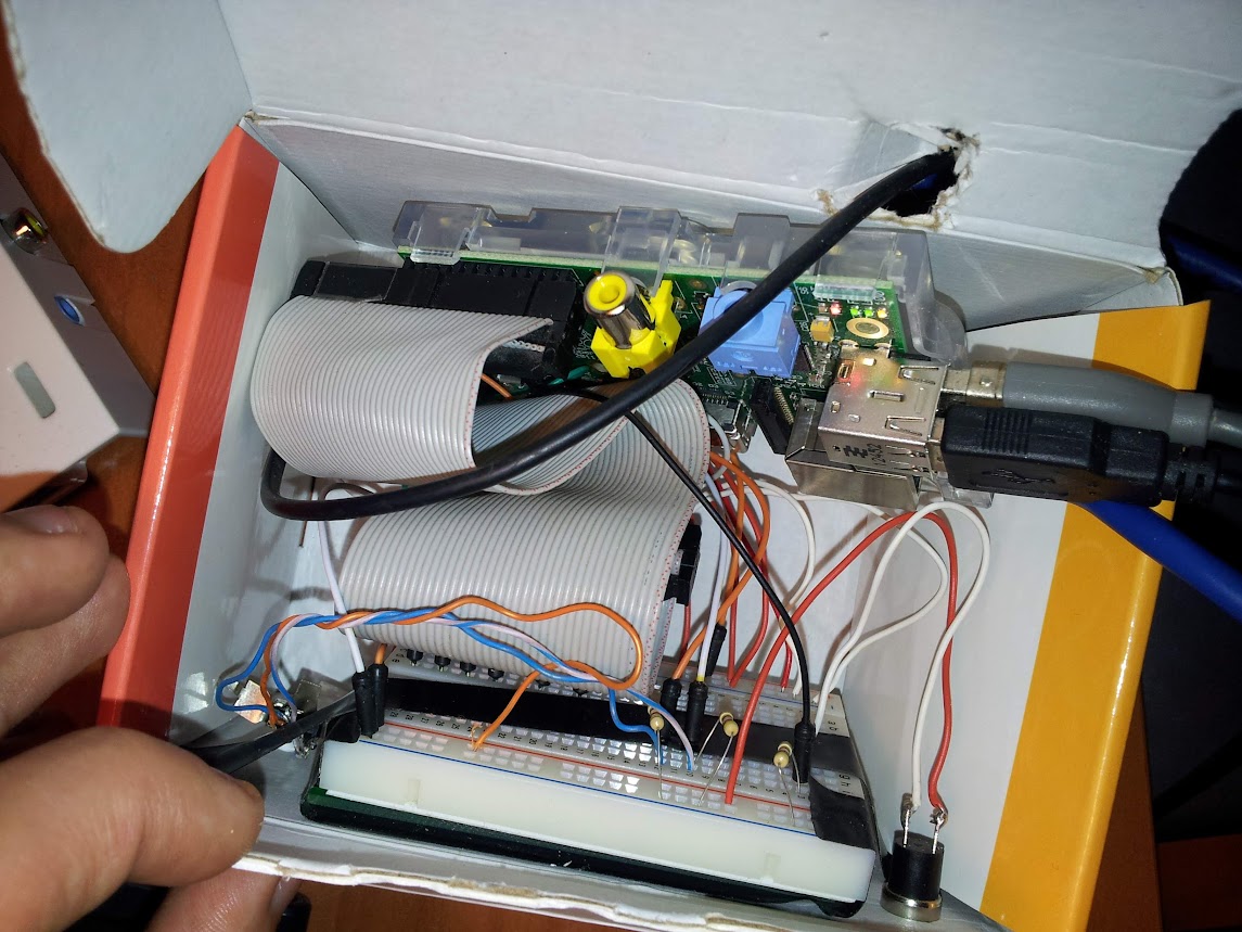
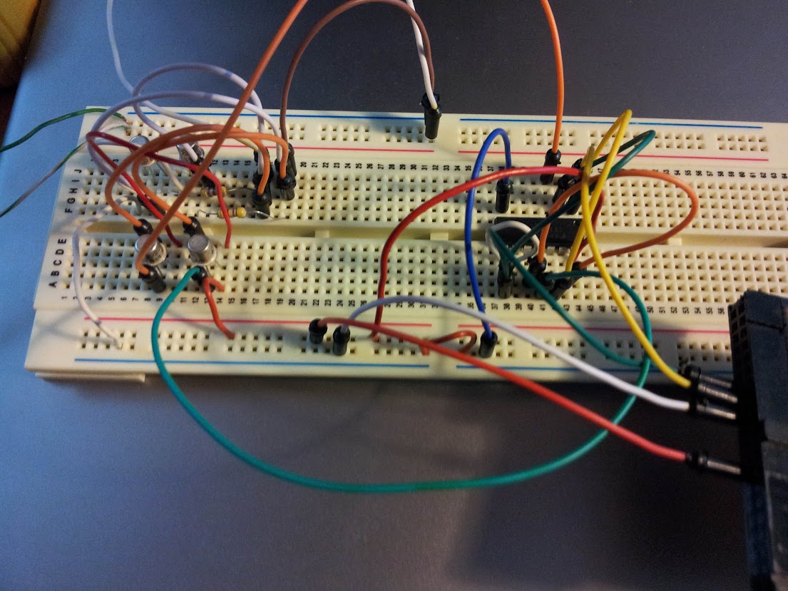
Eventually, I decided to build with my PI a motor driven webcam which could “follow” a face detected by opencv in the webcam stream. I disassembled a lot of things before finding a suitable motor but then I managed to connect it to the Raspberry GPIO (I had to play a little with electronics here, because i didn’t have a servo motor — if you need some information about this part, i’ll be happy to provide it, but i’m not so good with electronics thus the only thing I can say is that it works). Here’s a picture of the circuit:
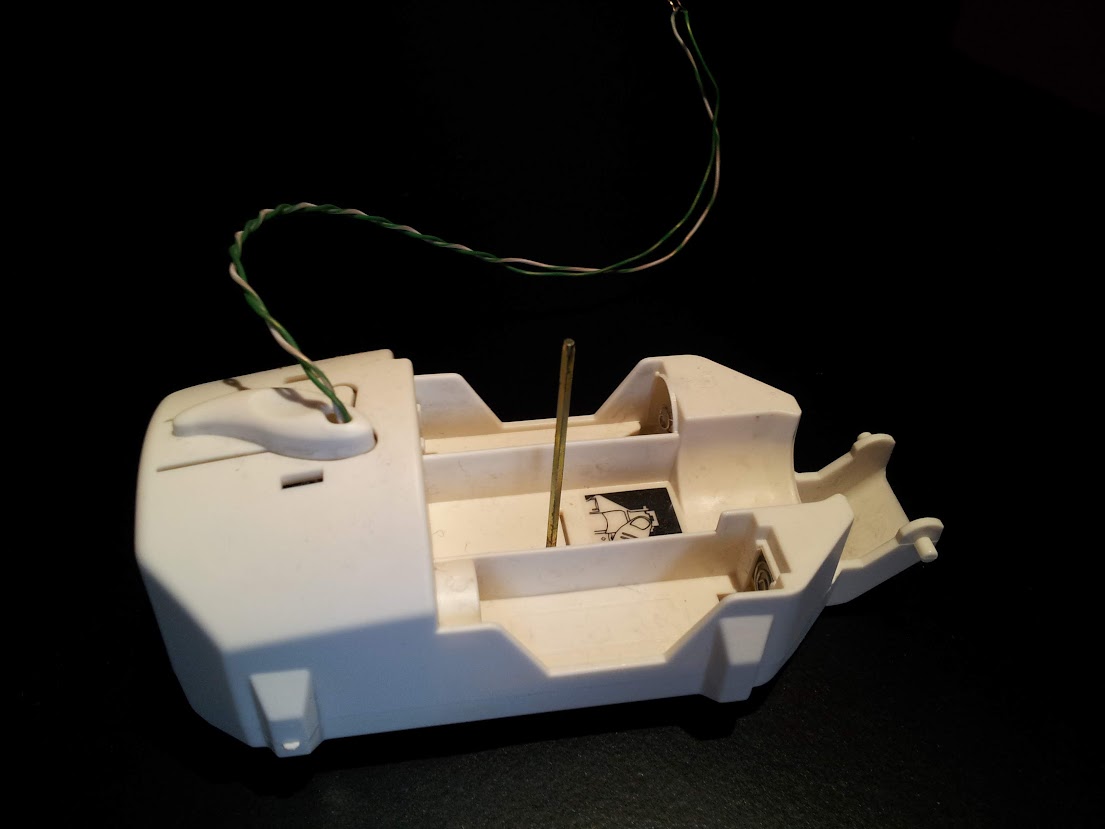
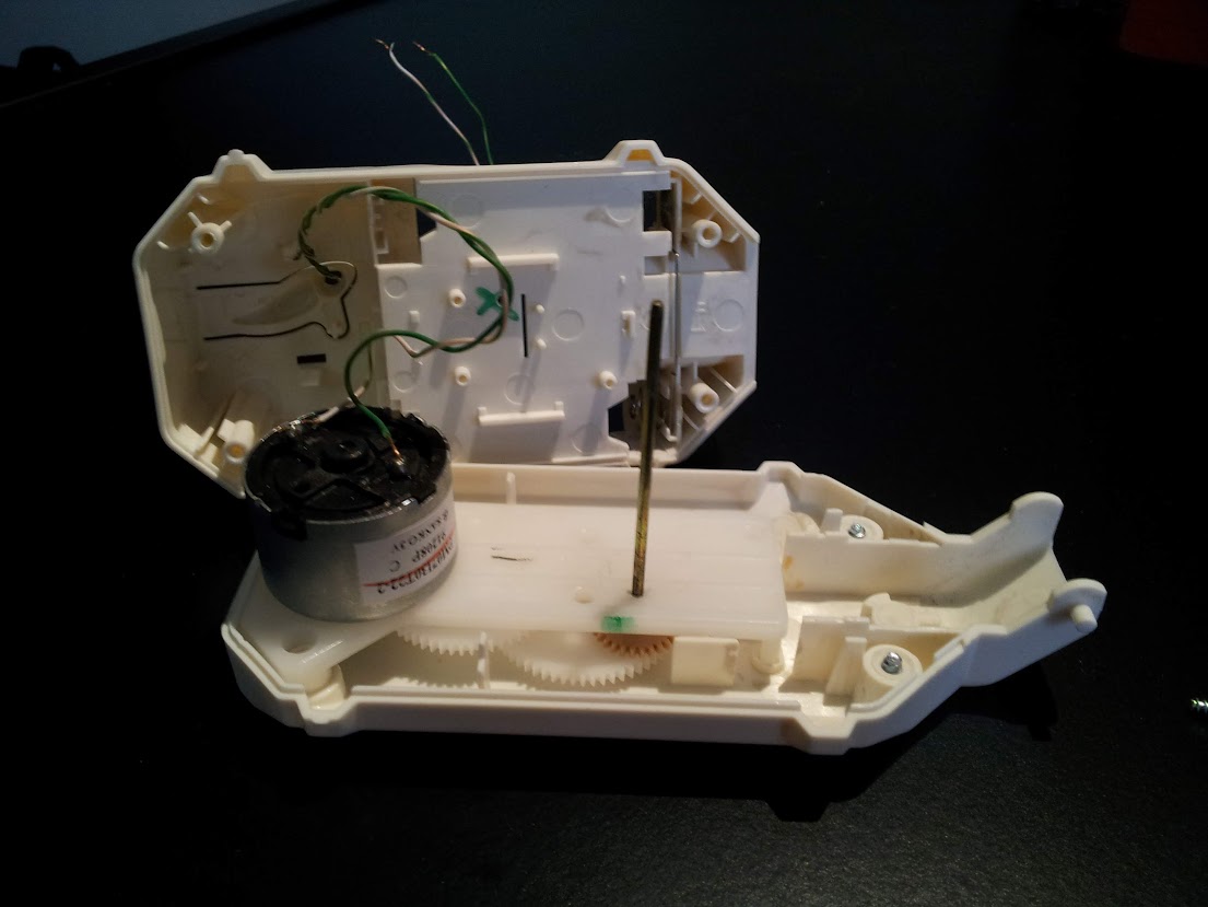
And here are some photos of the motor, to which I mounted an additional gear wheel.
Once the motor worked, I attached it to a webcam which i plugged into the PI, and then I joined the previous linked script with some GPIO scripting to achieve the goal, here is the result:
import RPi.GPIO as GPIO
import time,sys
import cv,os
from datetime import datetime
import Image

#GPIO pins i used
OUT0 = 11
OUT1 = 13

out0 = False #!enable line: when it's false, the motor turns, when it's true, it stops
out1 = False #!the direction the motor turns (clockwise or counter clockwise, it depends on the circuit you made)

def DetectFace(image, faceCascade):

    min_size = (20,20)
    image_scale = 2
    haar_scale = 1.1
    min_neighbors = 3
    haar_flags = 0

    # Allocate the temporary images
    grayscale = cv.CreateImage((image.width, image.height), 8, 1)
    smallImage = cv.CreateImage(
            (
                cv.Round(image.width / image_scale),
                cv.Round(image.height / image_scale)
            ), 8 ,1)

    # Convert color input image to grayscale
    cv.CvtColor(image, grayscale, cv.CV_BGR2GRAY)

    # Scale input image for faster processing
    cv.Resize(grayscale, smallImage, cv.CV_INTER_LINEAR)

    # Equalize the histogram
    cv.EqualizeHist(smallImage, smallImage)

    # Detect the faces
    faces = cv.HaarDetectObjects(
            smallImage, faceCascade, cv.CreateMemStorage(0),
            haar_scale, min_neighbors, haar_flags, min_size
        )

    # If faces are found
    if faces:
        #os.system("espeak -v it salve")
        for ((x, y, w, h), n) in faces:
            return (image_scale*(x+w/2.0)/image.width, image_scale*(y+h/2.0)/image.height)
            # the input to cv.HaarDetectObjects was resized, so scale the
            # bounding box of each face and convert it to two CvPoints
            pt1 = (int(x * image_scale), int(y * image_scale))
            pt2 = (int((x + w) * image_scale), int((y + h) * image_scale))
            cv.Rectangle(image, pt1, pt2, cv.RGB(255, 0, 0), 5, 8, 0)

    return False

def now():
    return str(datetime.now());

def init():
    GPIO.setmode(GPIO.BOARD)
    GPIO.setup(OUT0, GPIO.OUT)
    GPIO.setup(OUT1, GPIO.OUT)
    stop()

def stop(): #stops the motor and return when it's stopped
    global out0
    if out0 == False: #sleep only if it was moving
        out0 = True
        GPIO.output(OUT0,out0)
        time.sleep(1)
    else:
        out0 = True
        GPIO.output(OUT0,out0)

def go(side, t): #turns the motor towards side, for t seconds
    print "Turning: side: " +str(side) + " time: " +str(t)
    global out0
    global out1

    out1 = side
    GPIO.output(OUT1,out1)
    out0 = False
    GPIO.output(OUT0,out0)
    time.sleep(t)
    stop()

#getting camera number arg
cam = 0
if len(sys.argv) == 2:
    cam = sys.argv[1]

#init motor
init()

capture = cv.CaptureFromCAM(int(cam))
#i had to take the resolution down to 480x320 becuase the pi gave me errors with the default (higher) resolution of the webcam
cv.SetCaptureProperty(capture, cv.CV_CAP_PROP_FRAME_WIDTH, 480)
cv.SetCaptureProperty(capture, cv.CV_CAP_PROP_FRAME_HEIGHT, 320)
#capture = cv.CaptureFromFile("test.avi")

#faceCascade = cv.Load("haarcascades/haarcascade_frontalface_default.xml")
#faceCascade = cv.Load("haarcascades/haarcascade_frontalface_alt2.xml")
faceCascade = cv.Load("/usr/share/opencv/haarcascades/haarcascade_frontalface_alt.xml")
#faceCascade = cv.Load("haarcascades/haarcascade_frontalface_alt_tree.xml")

while (cv.WaitKey(500)==-1):
    print now() + ": Capturing image.."
    for i in range(5):
        cv.QueryFrame(capture) #this is the workaround to avoid frame buffering

    img = cv.QueryFrame(capture)
    hasFaces = DetectFace(img, faceCascade)
    if hasFaces == False:
        print now() + ": Face not detected."
    else:
        print now() + ": " + str(hasFaces)
        val = abs(0.5-hasFaces[0])/0.5 * 0.3
        #print "moving for " + str(val) + " secs"
        go(hasFaces[0] < 0.5, val)
    #cv.ShowImage("face detection test", image)
Of course I had to play with timing to make the webcam turn well, and the timings like everything strictly connected to the motor depends on your specific motor and/or circuit.
I’m writing to present my new Raspberry PI powered project, a simple motor controlled directly from the Raspberry’s GPIO. I’m very excited to think about the raspberry actually moving things.
My initial idea was building a webcam which could rotate to follow a face or an object, but i believe the Raspberry PI’s CPU is too limited for this purpose. Anyway i decided to try to make a webcam turning system which still is pretty cool.
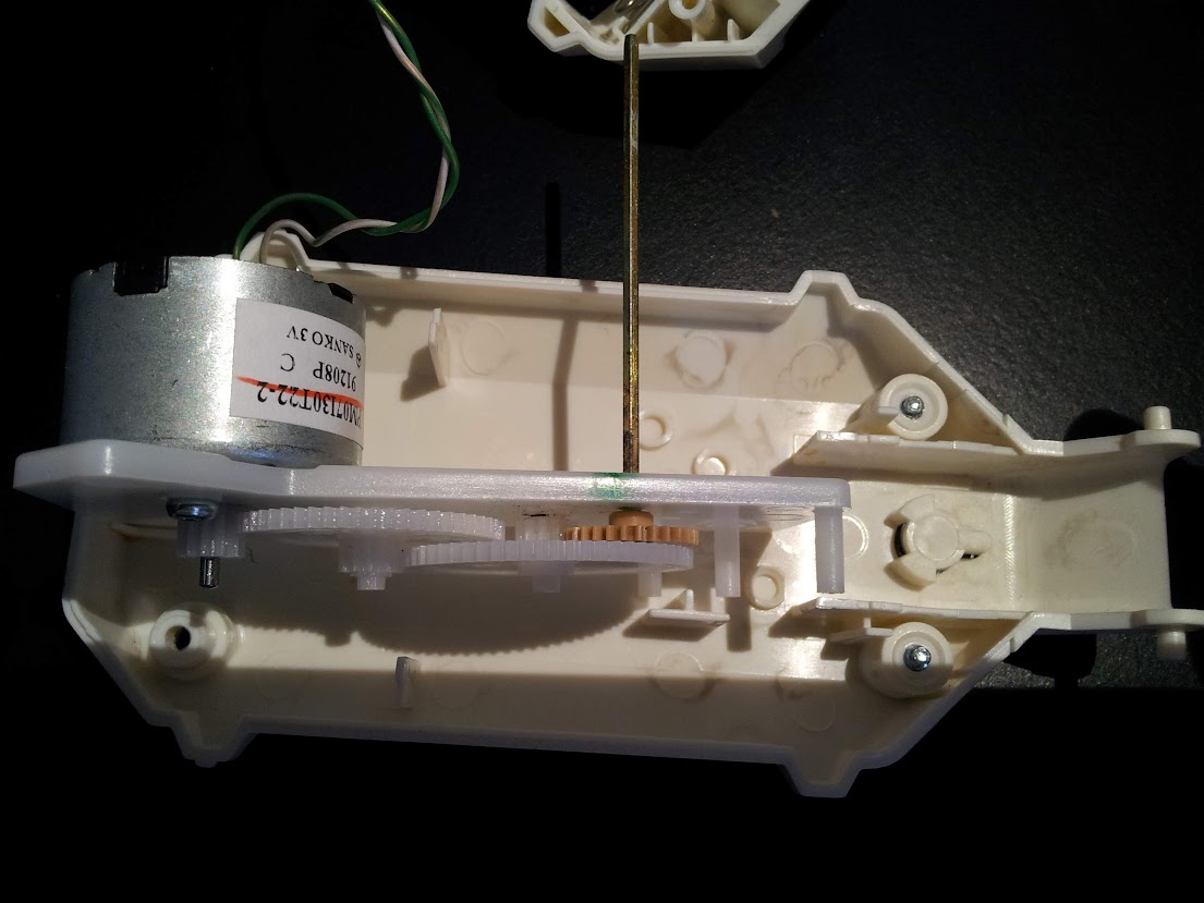
To do that I disassembled an old cd player, and used the laser moving motor system and some other recovered pieces to make it turn the webcam.
The following video (in italian) shows how it worked (not really well but hey, it does turn the webcam!).
The interesting thing in this project is that this kind of motors (from an old cd player) are capable of turning a webcam (which had been reduced in weight as much as i could) being powered only by the GPIO port. Not the 3V or 5V pins, which provide pretty much current, but the very GPIO pins of the board.
At this stage it is of course completely unusable, but like almost every project i’ve made so far, it just wants to be a proof of concept.
This is my last Raspberry PI project. It’s a simple alarm driven by a home-made door sensor which plays an alarm sound and sends me a message via twitter.
The video is in italian.
Here’s the python code which uses the tweepy library:
#!/usr/bin/python

# Import modules for CGI handling
import cgi, cgitb, time
import RPi.GPIO as GPIO
import os
import tweepy
import traceback

#fill these variables with your twitter app data
oauth_token = **
oauth_token_secret = **

consumer_key = **
consumer_secret = **

auth = tweepy.OAuthHandler(consumer_key, consumer_secret)
auth.set_access_token(oauth_token, oauth_token_secret)
api = tweepy.API(auth)

def send_tweet( api, what ):
    try:
        print "Tweeting '"+what+"'.."
        now = int(time.time())
        api.update_status('@danielenick89 '+ str(now) +': '+ what)
        print "Tweet id "+str(now)+ " sent"
    except:
        print "Error while sending tweet"
        traceback.print_exc()

GPIO.setmode(GPIO.BOARD)
GPIO.setup(11, GPIO.IN)
state = GPIO.input(11)
#print "Content-type: text/htmlnn";
while not GPIO.input(11):
    time.sleep(0.3)
#print "Activated.."
while GPIO.input(11):
    time.sleep(0.3)


send_tweet(api, "RasPI: Unauthorized door opening detected.")
os.system("mplayer alarm2/alarm.mp3");
In order to use this code you have to create an application on twitter, and then fill the variables (oauth_token, oauth_token_secret, consumer_key, consumer_secret) with the relative value you can find in the site after creating the app.